One switchboard that does two jobs saves a wall, a cable run and a week. It also puts the plant’s incomer and its motors in the same box, which is exactly where the design discipline has to start.
Key facts at a glance
- Busbar: 100 to 6300 A
- Short-time withstand: 50 / 65 / 80 kA for 1 s
- Separation: Form 3b or 4b
- Coordination: Type 2, IEC 60947-4-1
In this guide
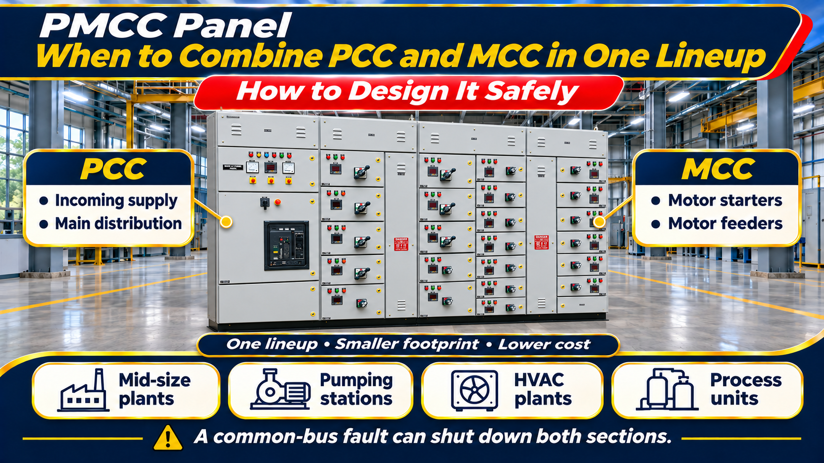
A power-cum-motor control centre (PMCC) combines the incoming supply and main distribution of a power control centre (PCC) with the motor starters of a motor control centre (MCC) in a single lineup. It is common in mid-size plants, pumping stations, HVAC plants and process units where a separate PCC and MCC would be overkill. Done well, a PMCC is compact and economical. Done badly, it is a board where a single fault takes out both the distribution and every motor. This article explains what a PMCC is, when to choose it, and how to design one so that it carries the advantages of both parents and the weaknesses of neither.
Ratings and construction details are drawn from published product documentation and common practice as of October 2026.
PCC, MCC and PMCC in one table
| Board | Incomer | Outgoings | Typical rating | Where |
|---|---|---|---|---|
| PCC | ACB from transformer or DG, bus-coupler | MCCB/ACB feeders to MCCs, APFC, PDBs, bus ducts | Up to 6300 A, 50 to 80 kA | Main electrical room |
| MCC | MCCB or ACB fed from the PCC | Motor starters: DOL, star-delta, soft-starter, VFD | Up to 6300 A, 50 to 80 kA | Near the process area |
| PMCC | ACB from transformer or DG | Both: distribution feeders and motor starters | Commonly 630 A to 4000 A | Plants with one electrical room and moderate motor count |
When a PMCC is the right answer
- Total load below roughly 2 to 3 MVA, with one or two transformers.
- Motor count in the tens, not the hundreds.
- One electrical room serving the plant, with motors within economical cable distance.
- Budget or space that will not support two lineups.
- Typical applications: water and wastewater pumping stations, HVAC and chiller plants, small process units, food and pharmaceutical utility blocks, cold storages, hotel and hospital utility plants.
When the motor count is large, when the process cannot tolerate a shutdown of distribution for motor work, or when motors are spread across a large site, a separate PCC and distributed MCCs remain the better design.
Design rules for a sound PMCC
- Separate the sections. Put the incomer and distribution feeders in one group of cubicles and the motor starters in another, joined by the main busbar. A bus-coupler or sectionaliser between them lets the motor section be isolated for work while distribution stays live, and vice versa.
- Form of separation by section. Form 3b is the usual minimum; Form 4b for the motor section where starters will be serviced live, often with drawout modules for critical drives.
- Short-circuit rating from the incomer. The whole board, including the motor section, must carry the fault level at the incomer, typically 50 kA or 65 kA for 1 s, verified by test.
- Protection coordination. Grade the incomer ACB, the distribution MCCBs and the motor feeder devices so that a motor fault clears at the starter, not at the incomer. Type 2 coordination to IEC 60947-4-1 for starters that must survive a short circuit.
- Metering and control supply. Incomer metering (multifunction meter, class 0.5 or 1 CTs), a control transformer with its own protection, and a control supply changeover if there is a DG.
- Cable alleys and entry. Power cables for distribution feeders are large; motor cables are many and small. Plan separate cable alleys or clearly segregated gland plates so that both can be terminated and maintained.
- Future space. Leave spare starter compartments and at least one spare distribution feeder; PMCCs grow.
Construction and ratings
A PMCC is built on the same platform as a PCC: 2.0 mm CRCA frames and 1.6 mm doors, electrolytic copper or aluminium busbars on SMC/DMC supports, 7-tank pre-treatment and powder coat, IP42 or IP54 indoors and IP55 or IP65 outdoors. Panel builders who manufacture both PCC and MCC lineups as type-tested assemblies to IEC 61439-1 and -2 typically offer the PMCC as a configuration of the same system: main busbars from 100 A to 6300 A, Icw of 50, 65 or 80 kA for 1 s, Form 1 to 4b, fixed, semi-drawout or drawout motor modules, and SCADA-ready metering and communication. The advantage of a single platform is that the design-verification report covers both halves of the board.
Operation and maintenance
- Treat the distribution and motor sections as separate assets in the maintenance system, with their own thermography and test schedules.
- Use the sectionaliser: isolate the motor section for starter work rather than working live under the distribution busbar.
- Keep the single-line diagram on the door current; PMCCs are modified more often than PCCs because motors are added.
- Record protection settings for both sections; a change on the incomer affects every motor’s coordination.
Common mistakes
- No sectionaliser, so any motor-section work requires a plant shutdown.
- Motor section rated for a lower fault level than the incomer “because the starters are small”.
- Distribution feeders and motor feeders sharing one cable alley with no segregation.
- Control supply taken from one phase of the main bus without a control transformer and protection.
- No spare space, forcing a second board within two years.
Frequently asked questions
Is a PMCC cheaper than a PCC plus MCC? Usually, because it saves an enclosure, a cable run between boards and floor space. The saving disappears if the plant later needs a separate MCC anyway.
Can a PMCC have drawout motor modules? Yes; a hybrid with drawout modules for critical drives and fixed compartments for the rest is common.
What Form of separation should a PMCC have? Form 3b as a minimum; Form 4b for the motor section where live servicing is expected.
Related reading
Disclaimer. This article is for general technical education and reflects common practice and published product documentation as of October 2026. Board selection, ratings, Form and protection coordination must be engineered for each plant to the applicable standards. Nothing here is a design specification.