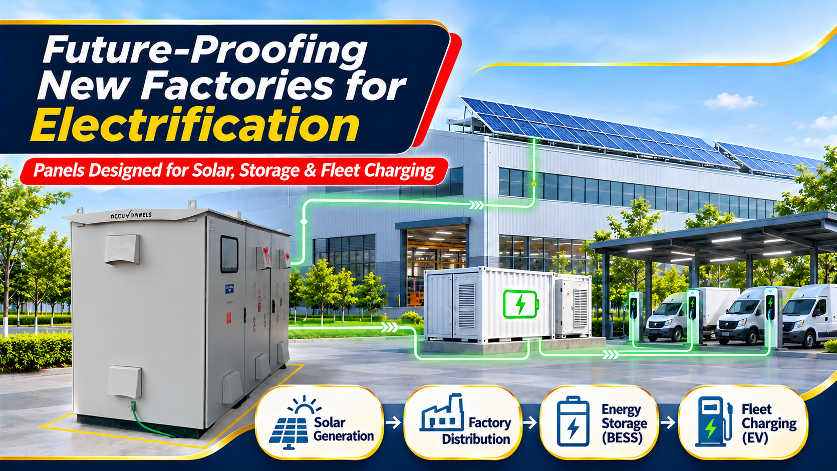
A factory buys its machines for ten years and its switchroom for thirty. The panels you order today will meet loads you have not bought yet: rooftop solar, a battery container, a charging bay full of forklifts and an energy-management system that wants a data point from every feeder.
This guide explains how to specify future-ready factory electrical panels for a greenfield or expanding plant in India, so that solar, battery energy storage (BESS), EV and forklift charging and AI-driven energy management can be added as feeders, not as a second switchroom. It includes a worked sizing and fault-level example for a 2 MVA plant and a checklist you can hand to a consultant or panel builder.
Figures reflect public government data, IEC standards and published product documentation as of November 2026. Calculations are illustrative.
Key facts at a glance
- Transformer loading: about 70–75 % at the managed future demand
- Voltage platform: Ui 1,000 V; 800 V AC sections for solar and BESS
- Fault level: include motor and inverter contribution — 65 kA 1 s in the 2 MVA example
- Metering: four-quadrant, Modbus TCP at incomer and every new-energy feeder
- EV circuits: own RCD ≤ 30 mA per point, Type B or Type A + 6 mA DC detection
In this guide
- The four additions a new factory should plan for
- Seven design decisions to lock in on day one
- Worked example: sizing a 2 MVA factory switchroom
- Solar-ready PCC and ACDB design
- BESS-ready: storage panels and the 650 V rule
- EV and forklift charging panels
- Digital switchgear and AI energy management
- Specification checklist for future-ready factory electrical panels
- Frequently asked questions
Machines and chargers can be swapped in a weekend; the transformer rating, main busbar, short-time withstand rating and switchroom floor space cannot. And the pressure to electrify is rising. India installed a record 44.61 GW of solar in FY 2025-26, of which about 16.3 GW was distributed solar, including 8.7 GW of rooftop systems. The Central Electricity Authority has notified a new BESS safety chapter that applies from 1 April 2027 to storage connected above 650 V, and has proposed co-located storage of at least 10 % of capacity for two hours on ground-mounted solar and wind projects commissioned after 1 July 2027. The Ministry of Power has told Parliament that AI data centres alone may add about 26.3 GW of load by 2031-32.
The four additions a new factory should plan for
| Addition | Typical arrival | What it needs from the LT panel | Panel that serves it |
|---|---|---|---|
| Rooftop or ground solar | Year 1–3 | Reserved PCC feeder, four-quadrant meter, zero-export and anti-islanding provision | Solar ACDB/DCDB, 800 V AC collection panel for larger plants |
| Battery energy storage | Year 2–5 | Bidirectional feeder, changeover logic, protected auxiliary supply for fire detection | Storage AC panel and container auxiliary board |
| EV, forklift and fleet charging | Year 1–5 | Dedicated feeder, one protective device and RCD per charging point, load management | EV charging LT panel or feeder pillar |
| Digital and AI energy management | Day 1 onwards | Communicating meters and relays, open protocols, time-stamped data | Intelligent MCC, PCC with gateway, smart APFC |
Seven design decisions to lock in on day one
- Headroom. Size the transformer for the managed future demand at about 70–75 % loading, keep 20–25 % spare feeder ways and one spare outgoing section footprint in the room.
- Voltage platform. Specify Ui 1,000 V on the main busbar system and allow an 800 V AC section where solar inverters or a storage PCS may collect. Insulation coordination at 800 V needs larger clearances and creepage than a 415 V board.
- Fault level for tomorrow, not today. Rate Icw and Ipk for transformer, motor and inverter contributions together (worked example below).
- Bidirectional metering. Four-quadrant multifunction meters with Modbus TCP at the incomer and every generation, storage and charging feeder.
- Harmonics. Detuned APFC with thyristor switching where drives, chargers and inverters will add harmonic current, plus space for an active filter.
- Changeover and control logic. Interlocked transfer between grid, DG and future storage, with zero-export and islanding logic designed in, not added by site wiring.
- Form of separation and withdrawability. Form 3b or 4b with withdrawable incomers on critical boards, so feeder work can be done with the rest of the board in service under the site’s isolation procedure. Separation is not arc containment; that is a separate arcing-fault test.
Worked example: sizing a 2 MVA factory switchroom
Assumptions: 11/0.433 kV Dyn11 transformer, uk 6.25 %, load loss 18 kW (assumed), infinite 11 kV source (conservative), 415 V nominal system, day-one maximum demand 1,250 kVA including a 750 kW LV motor group. Future additions: 1,000 kW rooftop solar on 415 V string inverters, a 500 kW / 1,000 kWh BESS, ten 22 kW AC fleet chargers and thirty 6 kW forklift chargers.
I = S ÷ (√3 × U)
Formula (IEC 60909-0:2016, Eq. 33): Ik″ = c·Un / (√3·Zk), with cmax = 1.10 for LV and the transformer impedance corrected by KT = 0.95·cmax / (1 + 0.6·xT). Peak check per IEC 61439-1 (Table 7 in the 2011 edition): Ipk ≥ n × Icw, with n = 2.2 above 50 kA.
| Step | Input / formula | Result |
|---|---|---|
| 1. Charging load | 10 × 22 kW + 30 × 6 kW = 400 kW at pf 0.95; every point at full current (demand factor 1) | 421 kVA |
| 2. BESS charging | 500 kW PCS at pf 0.95 | 526 kVA |
| 3. Unmanaged future demand | 1,250 + 421 + 526 = 2,197 kVA; ÷ 0.75 loading | 2,930 kVA transformer |
| 4. Managed future demand | Charging capped at 50 % by load management; BESS charged from solar or off-peak: 1,250 + 211 = 1,461 kVA; ÷ 0.75 | 1,947 kVA → 2,000 kVA |
| 5. Main incomer | 2,000 kVA ÷ (√3 × 433 V) | 2,667 A → 3,200 A ACB and busbar |
| 6. Rule-of-thumb fault level | 2,667 A × 100 ÷ 6.25 | 42.7 kA |
| 7. IEC 60909-0, transformer branch | ZT 5.86 mΩ, xT 0.062, KT 1.008, cmax 1.10 | 44.6 kA |
| 8. Motor contribution | 750 kW group, ILR/IrM = 5 | 7.3 kA |
| 9. Inverter contribution | Solar 1,391 A + PCS 696 A at 1.2 × rated (assumed; use the declared value) | 2.5 kA |
| 10. Total Ik″ (arithmetic sum) | 44.6 + 7.3 + 2.5 | 54.4 kA → specify 65 kA for 1 s |
| 11. Peak withstand | 2.2 × 65 kA (calculated ip ≈ 121 kA) | Ipk ≥ 143 kA |
| 12. Reserved feeders | Solar 1,391 A × 1.25; BESS 696 A × 1.25; EV panel 586 A | 2,000 A, 1,000 A and 800 A |
Engineering takeaway. The day-one load alone points to a 50 kA board. Add the motor group and the future inverters and the prospective fault current crosses 50 kA, so the main busbar, supports and incomer should be specified at 65 kA for 1 s from the start. Load management saves a full transformer size. Place the solar and storage feeders next to the incomer section so no busbar section carries more than the assembly’s rated current. Ask the panel builder for the design-verification basis of the 65 kA rating, not just the ACB breaking capacity.
Solar-ready PCC and ACDB design
Rooftop plants usually connect through a 415 V solar ACDB to a reserved PCC feeder; larger plants increasingly collect at 800 V AC through a dedicated panel and transformer. Provide a four-quadrant meter on the solar feeder, a zero-export or export-limit controller input, anti-islanding coordination with the DG, and Type 2 surge protection on the ACDB. For the 800 V case, a typical specification is an 800 V LT solar collection panel with Ui 1,000 V, main busbar from 630 A to 6,300 A, Icw 50 kA or 65 kA for 1 s, inverter feeders of 100 A to 400 A and Modbus metering, built to IEC 61439-1/2.
BESS-ready: storage panels and the 650 V rule
Factories add storage for peak shaving, DG reduction and backup. The LT scope is a storage AC panel (often sharing the solar collection line-up), an auxiliary board for the container’s HVAC, BMS and fire systems, and a changeover scheme that lets the PCS carry critical loads in island mode without paralleling with the grid unless the utility has approved it. Keep the fire-detection and suppression supply on a protected circuit. The voltage at which the storage connects matters in India: CEA’s new BESS chapter applies above 650 V from April 2027, while systems at or below 650 V follow the applicable standards. Decide the connection voltage early, because it changes the compliance path.
EV and forklift charging panels
Fleet charging is the load most often hung off the wrong board; give it its own feeder and panel. The installation rules for EV supplies (IEC 60364-7-722) assume every connecting point can run at full rated current unless load management limits it, require a dedicated circuit and its own overcurrent device per point, and require each AC point to have its own RCD of not more than 30 mA, either Type B or Type A with 6 mA DC fault detection. A 22 kW three-phase charger draws about 30.6 A at 415 V, so a 40 A device per point is typical. The EV charging infrastructure LT panel page shows how incomer ratings scale with charger mix, for example around 360 kW of DC chargers on an 800 A incomer.
Digital switchgear and AI energy management
An AI energy platform is only as good as the data the switchboard was built to provide. The proven route for an Indian plant is AC distribution with communicating devices: motor management relays in an intelligent MCC, Modbus TCP or IEC 61850 gateways at the PCC, and granular metering that lets software spot a derating compressor, an idling line or a capacitor step that has failed.
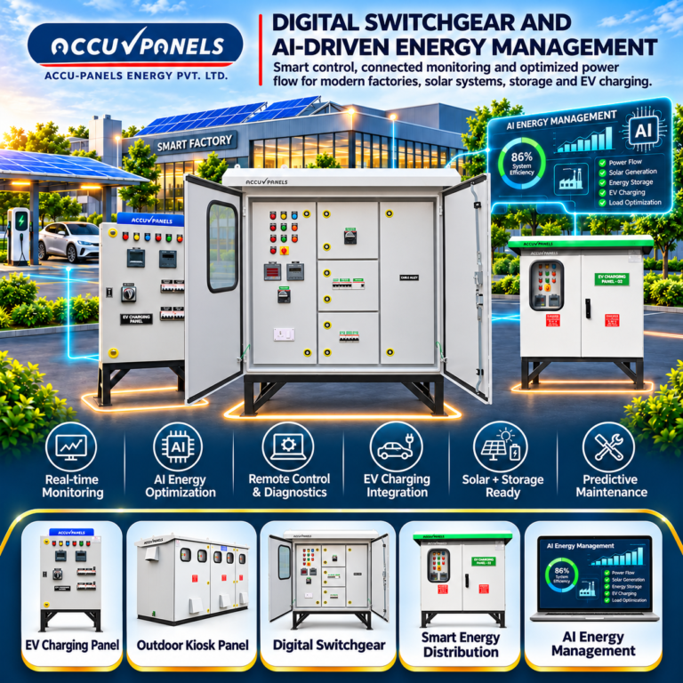
What global practice says. Published 2026 portfolios from leading international manufacturers converge on Ethernet-class communication inside LV switchgear, wireless busbar temperature sensing and energy management built into the distribution itself. Some promote DC distribution with semiconductor breakers; for most Indian plants, communicating AC switchgear remains the proven path.
Specification checklist for future-ready factory electrical panels
Most of these items add only a few per cent to the switchboard cost. The 65 kA platform, spare ways and communicating meters cost far less on day one than a second switchroom, replaced busbar supports or retrofitted metering later.
- Transformer sized on managed future demand at ≤ 75 % loading; load-management philosophy written into the specification.
- Prospective fault level calculated with motor and inverter contributions; Icw stated with duration and Ipk in kA peak.
- Ui 1,000 V platform; 800 V AC section where solar or storage may collect.
- Reserved, rated feeders and cable routes for solar ACDB, storage AC panel and EV charging panel.
- Four-quadrant Modbus TCP metering at incomer and every generation, storage and charging feeder.
- Detuned APFC with thyristor switching and active-filter provision.
- Interlocked grid–DG–storage changeover with zero-export and islanding logic.
- Form 3b/4b and withdrawable incomers on critical boards.
- Assemblies design-verified to IEC 61439-1/-2 (by test, comparison or assessment as the standard allows), routine-tested, with editable drawings and test certificates.
Frequently asked questions
What makes a factory electrical panel future-ready?
Spare capacity on the transformer and busbar, a fault rating that includes future inverters and motors, reserved feeders for solar, storage and charging, four-quadrant communicating meters and open protocols for energy management.
How much spare capacity should a new LT panel have?
Common practice is 20–25 % spare feeder ways and a transformer loaded to about 70–75 % at the managed future demand.
Does rooftop solar or BESS increase the fault level of an LT panel?
Yes, modestly. Inverters contribute a limited fault current, typically close to their rating, and motors contribute more. Together they can push a board past its rating, so include them in the IEC 60909-0 calculation.
Which RCD is needed for EV chargers in a factory?
Each AC charging point needs its own RCD of not more than 30 mA, either Type B or Type A combined with 6 mA DC fault detection, unless the charger already provides that detection.
Related reading
Disclaimer. This article is for general technical education and reflects public government data, IEC standards and published product documentation as of November 2026. The worked example uses stated assumptions; real plants must be engineered from site data to IEC 61439, IEC 60909-0, IEC 60364-7-722, IEC 62933 and the applicable CEA regulations. Nothing here is a design specification or a guarantee of savings.