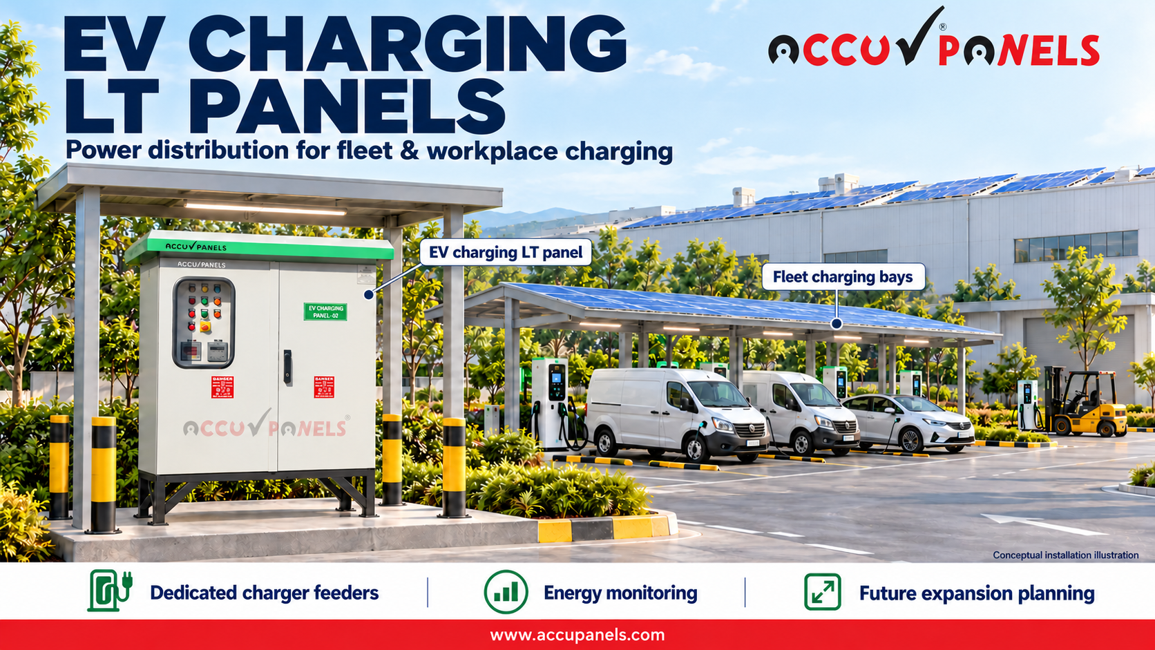
The DISCOM does not inspect your chargers. It inspects your switchboard. Electrical readiness is the part of an EV hub nobody photographs and everybody waits for.
“Electrical readiness” is the phrase charge-point operators now use for everything between the utility connection and the charger input terminals: the connection itself, the transformer where needed, the main LT panel, the charger feeders, protection, metering, power-factor correction, earthing and surge protection. For sites from a 60 kW car-park cluster to a 1 MW highway hub, this article sets out how the load is estimated, how the panel basket is sized, what protection the charger classes demand and how the site passes inspection the first time.
Figures reflect public Indian guidelines, international engineering practice and published product documentation as of October 2026.

Future-ready factory switchroom campus
Step 1: Estimate the real load, not the nameplate sum
What the standard says
IEC 60364-7-722:2015, clause 722.311, sets two rules for EV installations:
-
Each connecting point is assumed to run at its rated current in normal use, so the final circuit has a demand factor of 1.
-
Because all connecting points can be used at the same time, the diversity factor of the distribution circuit is 1. It may be reduced only where load control is available.
This is stricter than ordinary distribution loads. Where the panel builder and user have not agreed the actual load currents, IEC 61439-2:2011 (5.4 and Table 101) lets the builder assume an outgoing-circuit loading of 0.9 for 2–3 circuits, 0.8 for 4–5, 0.7 for 6–9 and 0.6 for 10 or more. A 12-way charger board verified on that default is only proven for about 60 % of the load the chargers can draw at the same time.
Design rule: State a rated diversity factor (RDF) of 1.0 for charger feeders in the panel specification (IEC 61439-1:2011, 5.4). Lower it only where a load-management system enforces a site power cap.
Per-charger input current
For three-phase chargers at 415 V:
| Charger | Assumptions | Input current IBI_B | Typical feeder MCCB |
|---|---|---|---|
| 7.4 kW AC, single-phase | 230 V | 32 A | 40 A |
| 22 kW AC, three-phase | PF 0.99 | 31 A per phase | 40 A |
| 60 kW DC | PF 0.99, η 0.95 | 89 A | 125 A |
| 120 kW DC | PF 0.99, η 0.95 | 178 A | 250 A |
| 240 kW DC | PF 0.99, η 0.95 | 355 A | 400 A |
| Site type | Charger mix | Design demand | Supply (Gujarat) | Main panel |
|---|---|---|---|---|
| Housing society or office car park | 8–20 AC, 7.4–22 kW | 60–150 kW with load management | LT, 3-phase 400 V (up to 150 kVA if opted) | PDB, 250–400 A incomer |
| Commercial hub | 4 × 60 kW DC + 10 × 22 kW AC | ~460 kW unmanaged; 300–400 kW with a power cap | 11 kV with own transformer (630–800 kVA) | PCC 800–1250 A; Icw from fault study (typically 25–36 kA at this size) |
| Highway hub | 4–8 × 120–240 kW DC | 0.6–1.2 MW | 11 kV, 1000–1600 kVA transformer | PCC 1600–2500 A; Icw 50 kA (check Ipk) |
| Fleet or bus/truck depot | 20–50 points, 50–400 kW | 1–5 MW, built in stages | 11 kV up to 4000 kVA contract demand; 33 kV above | PCC 2500–6300 A, bus duct from transformer; Icw 65 kA or higher |
National guidelines require heavy-vehicle fast-charging sites to carry at least two chargers of 240 kW or more and bus depots to provide at least 240 kW, which pushes most highway and depot projects into the HT-connected category.
Step 2: Secure the connection
Under the 2024 amendment to the consumer-rights rules, a separate connection for EV charging is a right, with new-connection timelines of 3 days in metropolitan areas, 7 in other municipal areas and 15 in rural areas (longer where network extension is needed). The 2024 charging-infrastructure guidelines cap the supply tariff at the average cost of supply until March 2028, with a lower rate in solar hours. The DISCOM will state the fault level at the point of supply; the panel must be rated above it, not at a catalogue default.
Step 3: The panel basket, sized
- Main LT panel (PCC). Incomer ACB or MCCB with electronic release, Icw 50 or 65 kA for 1 s, multifunction meter with Modbus, Form 3b or 4b separation for sites that must stay live during maintenance. Design ambient 45 to 50 °C.
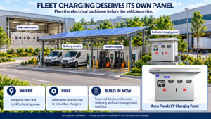
- Charger feeder panel. One MCCB per charger (63 to 400 A), sized for the charger’s input current plus 25 per cent for continuous duty. A dedicated EV charging LT panel typically provides incomers from 250 to 4000 A and charger feeders from 63 to 400 A on an IEC 61439-1/-2 platform with Type A/B RCDs, Type 1+2 or Type 2 surge protection and detuned APFC as options.
- Distribution boards. Separate boards for canopy lighting, CCTV and network, kiosk or café, HVAC; 63 to 400 A, IP54 indoor or IP65 outdoor.
- Feeder pillar. For bays far from the electrical room: IP55/IP65, sloped canopy, breathers and drains, C5 coating on open ground, IEC 61439-5.
- APFC. DC chargers are rectifier loads; use detuned 7 per cent banks and thyristor switching so that correction follows a charging session, not a fifteen-minute average.
- Solar ACDB/DCDB where canopy solar or storage is present: IP65, Type 2 SPD, anti-islanding contactor.
Calculate the fault level and size the panel
On an HT-fed site, the transformer limits the fault current at the LT busbar. IEC 60909-0:2016 gives the method:
-
Transformer impedance, Formula (7):
ZT=ukr100%⋅UrT2SrTZ_T = \frac{u_{kr}}{100\%}\cdot\frac{U_{rT}^2}{S_{rT}}with the resistive part taken from load losses, Formula (8): RT=PkrT/(3IrT2)R_T = P_{krT}/(3 I_{rT}^2).
-
Impedance correction factor for network transformers, Formula (12a):
KT=0.95⋅cmax1+0.6 xTK_T = 0.95\cdot\frac{c_{max}}{1+0.6\,x_T}-
Initial symmetrical short-circuit current, Formula (33):
Ik′′=c Un3 ZkI”_k = \frac{c\,U_n}{\sqrt{3}\,Z_k}Here cmaxc_{max} = 1.05 for LV systems with a +6 % voltage tolerance, or 1.10 with +10 % (Table 1).
-
Peak short-circuit current, Formula (56), with κ from Formula (57):
ip=κ2 Ik′′,κ=1.02+0.98 e−3R/Xi_p = \kappa\sqrt{2}\,I”_k, \qquad \kappa = 1.02 + 0.98\,e^{-3R/X}Worked results (415 V, cmaxc_{max} = 1.05, infinite 11 kV source: a conservative assumption)
Transformer ukru_{kr} / assumed load loss IrTI_{rT} (433 V) Ik′′I”_k at LT bus R/X ipi_p Minimum panel rating 1000 kVA 5 % / 10.5 kW 1333 A 27.7 kA 0.22 60 kA Icw 36 kA, Ipk ≥ 76 kA 1600 kVA 6.25 % / 14 kW 2133 A 35.7 kA 0.14 84 kA Icw 50 kA, Ipk 105 kA 2000 kVA 6.25 % / 17 kW 2667 A 44.6 kA 0.14 105 kA Icw 50 kA is borderline on peak; specify 65 kA 2500 kVA 6.25 % / 20.5 kW 3333 A 55.8 kA 0.13 133 kA Icw 65 kA, Ipk ≥ 143 kA -
Step 4: Protection that matches the charger class
| Charger class | Residual-current protection | Notes |
|---|---|---|
| AC Mode 3 (7.4 to 22 kW) | Type B RCD 30 mA, or Type A RCD plus a 6 mA DC-leakage detector (RDC-DD) in the charger | Per circuit; confirm which device the charger already contains |
| DC fast charger (50 to 400 kW) | Type B RCD 100 to 300 mA on the AC input, or protection integrated by the charger manufacturer | Isolation monitoring on the DC side is the charger’s responsibility |
| Any outdoor site | Type 1+2 SPD at the incomer, Type 2 at the charger panel if more than about 10 m away | Open-air sites on long overhead lines are lightning-exposed |
Earthing is the most common inspection failure: a dedicated earth grid, bonding of every charger pedestal and feeder pillar, and TN-S downstream of the main panel with the neutral earthed only at the source.
Surge and lightning protection
-
The MoP 2024 safety checklist calls for Type 1 and Type 2 surge protection (IS/IEC 62305-4, IEC 61643-12) requires a lightning protection system for EV charging stations.
-
Fit a Type 1+2 SPD at the PCC incomer, and a Type 2 SPD at any charger panel or feeder pillar more than about 10 m of cable away. The 10 m figure is common SPD practice; confirm it against the SPD manufacturer’s protective distance.
Earthing and bonding: the most common inspection failure
-
CEA 2023 Regulation 125(3) requires an earth continuity monitoring system that disconnects the supply if the earth connection to the vehicle becomes ineffective. Regulation 125(5) requires an equipotential protective earth between the supply earth terminal and the vehicle’s conductive parts.
-
Provide a dedicated earth grid designed to IS 3043. Bond every charger pedestal, canopy steel and feeder pillar to it. Keep the system TN-S downstream of the main panel, with neutral and earth joined only at the source (the transformer star point and MET).
-
Other CEA 2023 site rules (Regulation 124):
-
four-core cable for three-phase charging points (124(15));
-
underground cables avoided under vehicle passages, or buried at least 1 m deep (124(17));
-
protection against uncontrolled reverse power flow (124(8)).
-
Step 5: Pass inspection first time
Panel compliance file (IEC 61439)
-
Design verification evidence (IEC 61439-1:2011, clause 10, Table D.1): strength of materials, degree of protection, clearances and creepage, protection against electric shock, temperature rise (10.10), dielectric properties, short-circuit withstand (10.11) and EMC. Verification may be by test, by comparison with a tested reference design, or by assessment. Temperature rise by calculation is limited to single-compartment assemblies up to 630 A or assemblies up to 1600 A (10.10.1). CPRI type-test reports cover the test route.
-
Routine verification certificate for each panel (clause 11): IP, clearances, protective-circuit continuity, built-in components, wiring and connections, terminals, mechanical operation, dielectric test, and wiring and functional checks (11.2–11.10).
-
A rating label and documentation showing Ue, InA, Inc, Icw/Ipk, RDF 1.0, IP, form of separation and the agreed special service conditions.
Charger and system documents
-
Charger type-test certificates under the IS 17017 series from an NABL-accredited lab (MoP Guidelines 2024, Annexure I–II):
-
DC chargers: IS 17017-23, with CCS2 connectors to IS 17017-2-3;
-
AC parkbay chargers: IS 17017-1 with IS 17017-2-2.
-
-
OCPP for the charge management system, as the guidelines encourage.
-
Single-line diagram and schematics drawn to IEC 61082-1, with reference designations matching the labels on site.
-
Earthing layout and earth-resistance test record.
-
A fire detection and alarm system under CEA 2023 Regulation 126(2), and charger enclosures of fire-retardant, self-extinguishing, halogen-free material (126(1)).
Commissioning record
-
Insulation resistance, polarity and phase sequence.
-
Continuity of protective conductors.
-
RCD trip times at rated residual current and the DC fault-detection test.
-
Tests specified in the RCD and charger manufacturers’ instructions, which the station owner must record (CEA 2023 Regulation 127).
-
Breaker setting record and selectivity study.
-
Meter, CT ratio and communication checks.
-
Labelling: every feeder marked with the charger it feeds; voltage and arc-flash warnings on the PCC.
Frequently asked questions
Do I need an HT connection for a highway hub? Usually yes above about 500 kW; the DISCOM’s LT limit and the guideline minimum of two 240 kW chargers push most highway sites to 11 kV.
Can one panel feed chargers and site services? Yes, with separate sections or boards so that a charger fault does not darken the plaza, and with selectivity designed between feeder and incomer.
Why detuned APFC rather than plain capacitors? Rectifier harmonics can resonate with plain capacitors; detuned reactors shift the resonance away from the dominant harmonics.
Common mistakes we see
-
Using default diversity. Using office-style diversity for charger feeders means the busbars and incomer overheat once the site is busy. Specify RDF 1.0 or a load-management cap.
-
Copying a “50 kA” catalogue rating without checking the peak current from a 2000 kVA or larger transformer.
-
Fitting a Type AC or plain Type A RCD on AC chargers without built-in 6 mA DC detection.
-
Running a PEN conductor (TN-C-S) to outdoor charger pedestals, or leaving pedestals and canopy steel unbonded.
-
Plain capacitor banks on sites with rectifier loads, which risk resonance and capacitor failure.
-
No spare ways or floor space. Charger counts only go up. Reserve 20–30 % spare feeder capacity and space for at least one more section.
Frequently asked questions
Do I need an HT connection for an EV charging hub in Gujarat?
Yes, above 150 kVA/kW of contract demand. The GERC Supply Code allows three-phase LT up to 100 kVA, or 150 kVA if you opt for it. Above that, supply is at 11 or 22 kV up to 4000 kVA, and at 33 kV or above beyond that. Two 240 kW chargers alone exceed the LT limit.
What diversity factor should I use for EV chargers?
1.0 unless a load-management system limits site power (IEC 60364-7-722, 722.311). With load management, size for the enforced cap plus a margin, and make sure the cap cannot be bypassed.
Which RCD does an AC EV charger need?
A 30 mA RCD per connecting point, at least Type A. Add DC fault protection: either a Type B RCD, or a Type A RCD with 6 mA DC detection, unless the charger already includes it (722.531.2.101).
What Icw rating should an EV charging panel have?
Whatever your fault study gives, never a default. As a guide, a 1600 kVA transformer at 6.25 % impedance gives about 36 kA r.m.s. and 84 kA peak at the LT bus, so 50 kA Icw / 105 kA Ipk is adequate. At 2000 kVA, move to 65 kA.
Can one panel feed chargers and site services?
Yes, with separate sections or boards so a charger fault does not black out the plaza. Design selectivity between feeder and incomer breakers, and between charger RCDs and any upstream RCD.
Why detuned APFC rather than plain capacitors?
Rectifier harmonics can resonate with plain capacitors. A 7 % reactor tunes the bank to about 189 Hz, below the 5th harmonic, and protects the capacitors. Check charger PF first: modern active-front-end units may need little correction.
Which form of separation is right for an EV hub?
Form 3b or 4b under IEC 61439-2, so individual charger feeders can be isolated and worked on while the rest of the site keeps charging.
Which standards apply to the LT panel?
IS/IEC 61439-1 and -2 for the assembly, IEC 60947-2 for breakers, IEC 60529 for IP, IEC 61439-5 for feeder pillars, IEC 60364-7-722 for the EV installation, and the CEA Safety Regulations 2023, Chapter XI.
Plan your EV hub with Accu Panels
Send us your charger list and DISCOM fault level. We’ll return a free load and fault-level calculation, SLD and panel GA drawing
Related reading
Disclaimer. This article is for general technical education and reflects public guidelines, international engineering practice and published product documentation as of October 2026. Load estimation, protection selection, earthing and panel ratings must be engineered for each site to IEC 60364-7-722, IEC 61439, IEC 61851, the IS 17017 series, CEA regulations and the distribution licensee’s requirements. Nothing here is a design specification.