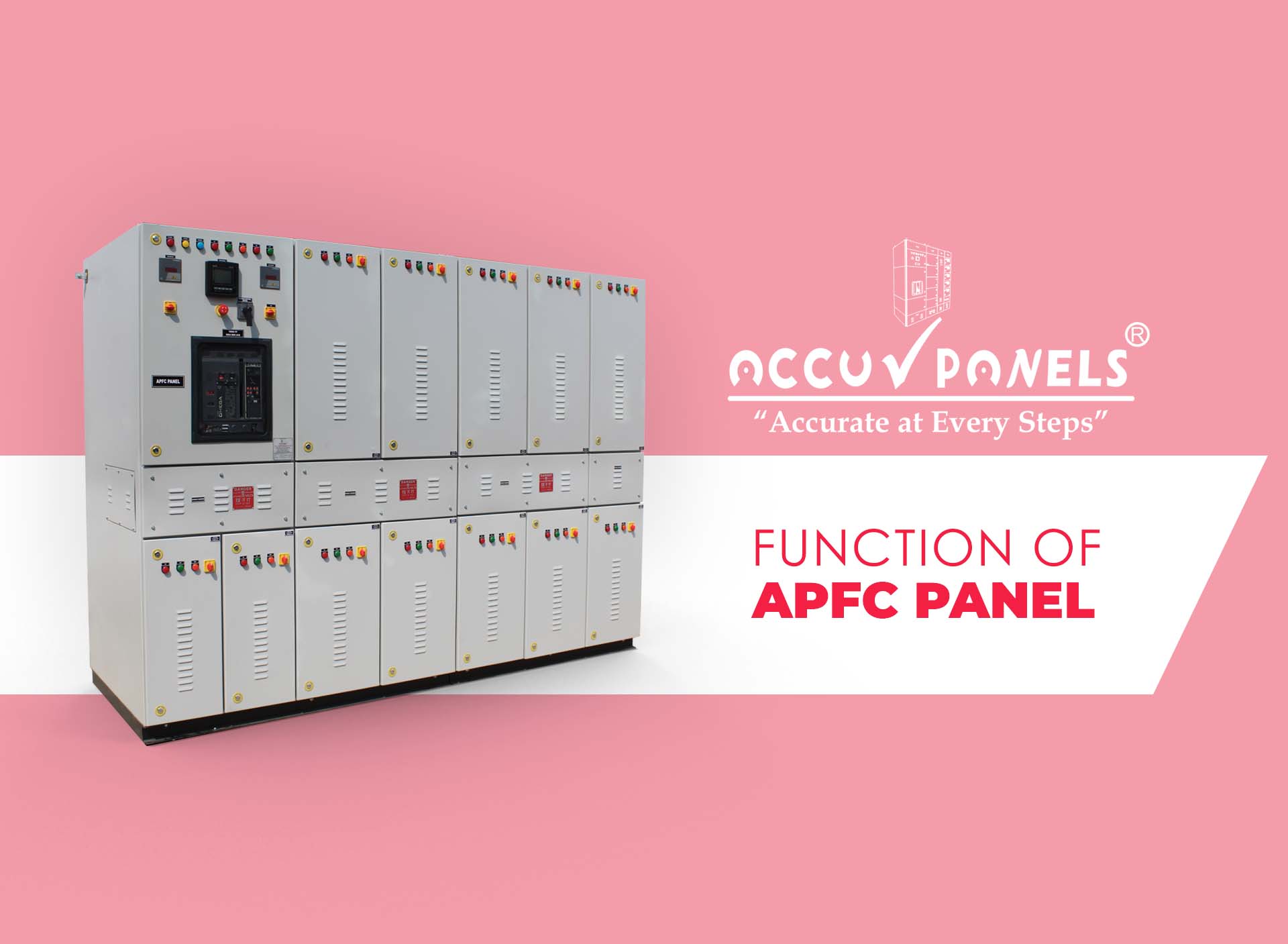
The function of an APFC panel (Automatic Power Factor Correction panel) is to keep a plant’s power factor close to unity — typically 0.98 to 0.99 lagging — by switching capacitor banks in and out automatically as the reactive load changes. Most industrial load is inductive (motors, transformers, welding sets, discharge lighting), which draws reactive current that does no useful work but still loads cables, transformers and the utility network. Electricity boards penalise low power factor and reward high power factor; the APFC panel is the equipment that earns the reward without an operator touching a switch.
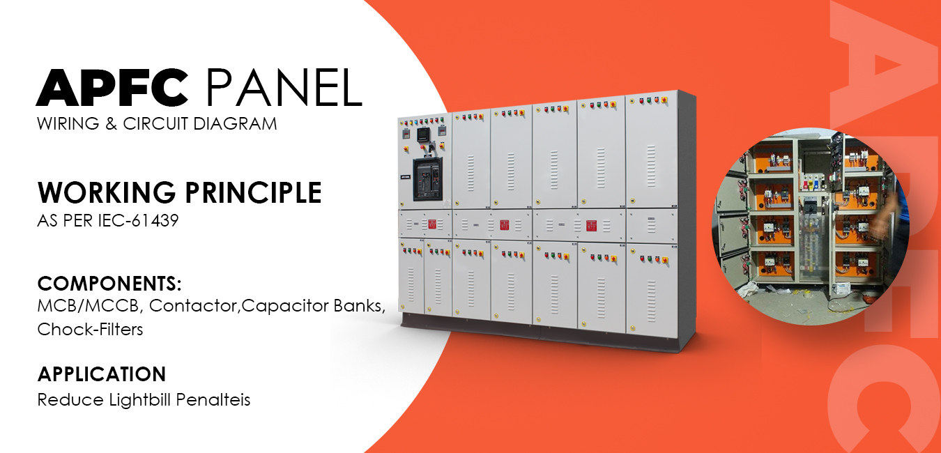
How an APFC panel works
An APFC relay (automatic power factor controller) measures the load current through a CT and the busbar voltage, calculates the reactive power (kVAr) and the actual power factor, and compares it with the target set on the relay. When the power factor falls below target, the relay closes the next capacitor step through a capacitor-duty contactor or a thyristor switch; when the load drops and the power factor would go leading, it disconnects steps. Steps are switched in a rotation so all capacitors age evenly, and a discharge time is enforced before any capacitor is re-energised. Modern relays also display THD, temperature and step health, and communicate over Modbus to the plant energy management system.
Why a low power factor costs money
- Utility penalties or lost incentives: most Indian DISCOMs charge a penalty below about 0.90 and give an incentive above 0.95–0.99.
- Higher kVA demand: the same kW at 0.80 PF needs 25 % more kVA than at unity, which means a larger contract demand and transformer.
- Losses and voltage drop: the extra reactive current heats cables and transformers (I²R) and depresses voltage at the motor terminals.
- Released capacity: correcting from 0.80 to 0.98 frees roughly 18 % of transformer and switchgear capacity for new load.
How much kVAr is needed?
Required kVAr = kW × (tan φ1 − tan φ2), where φ1 is the existing power-factor angle and φ2 the target angle. The table gives the multiplier for common cases.
| Existing PF | Multiplier to reach 0.95 | Multiplier to reach 0.99 | Example: 500 kW load → kVAr for 0.99 |
|---|---|---|---|
| 0.70 | 0.69 | 0.88 | 440 kVAr |
| 0.75 | 0.55 | 0.74 | 370 kVAr |
| 0.80 | 0.42 | 0.61 | 305 kVAr |
| 0.85 | 0.29 | 0.48 | 240 kVAr |
| 0.90 | 0.16 | 0.34 | 170 kVAr |
In practice the bank is sized from the maximum-demand readings or a 7-day load survey, with 10–15 % margin, and split into steps small enough (5–50 kVAr) to follow the load without hunting.
Types of APFC panels
- Contactor-switched APFC: capacitor-duty contactors with pre-charge resistors; economical, 5–10 s response; suits steady loads such as textile mills and pumping stations.
- Thyristor-switched (real-time / RTPFC): switches within one cycle, transient-free and wear-free; suits welding, cranes, presses, lifts and other fast-changing loads.
- Detuned APFC: a 7 % (189 Hz) or 14 % (134 Hz) reactor in series with each capacitor step blocks harmonic resonance where VFDs, UPS or rectifiers exceed 15–20 % of load; capacitors are rated 480–525 V to withstand the reactor’s voltage rise.
- Fixed compensation: a capacitor permanently connected across a large motor or transformer no-load current, used together with the APFC for the variable part.
Standards for APFC panels
The assembly is designed and routine-tested to IEC 61439-1/2 (IS/IEC 61439); power capacitors to IEC 60831-1/2; reactors to IEC 60076-6; capacitor-duty contactors and switchgear to IEC 60947; and the enclosure’s degree of protection to IEC 60529 (IP42/IP54 indoor with forced ventilation). Accu-Panels APFC panels share the CPRI type-tested platform of our PCC and MCC panels — see what IEC 61439 type-tested really means.
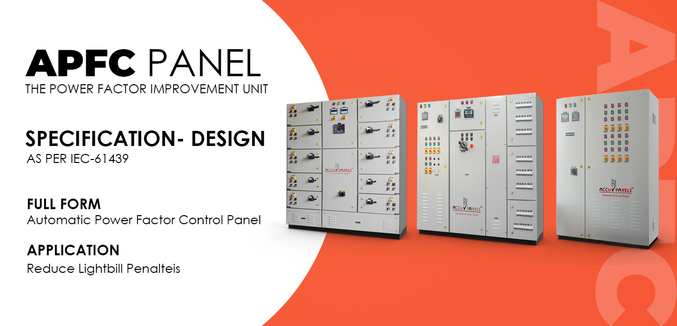
Construction of an Accu-Panels APFC panel
Metal-clad, totally enclosed, floor-mounted cubicle in 2.0 mm CRCA with 1.6 mm doors, 7-tank pre-treated and powder coated; MCCB incomer; HRC fuse or MCCB protection per step; capacitor-duty contactors or thyristor modules; heavy-duty cylindrical or box-type capacitors with discharge resistors; detuned reactors where specified; APFC relay with 6 to 14 steps; thermostat-controlled ventilation with filters; designed for 45–50 °C ambient and 80 % humidity. Ratings from 20 kVAr to 3000 kVAr — full specifications on our APFC panel product page.
Where APFC panels are used
Dairy, plastics and packaging plants, refrigeration and cold storage, batching plants, chemical and pharmaceutical units, textile mills, cement and steel plants, commercial buildings, hospitals, data centres, and solar and hybrid plants — anywhere motors, transformers and drives create reactive load. APFC panels are usually fed from the PCC panel and installed next to the MCC.
Frequently asked questions
What power factor should I target?
0.98–0.99 lagging. Going to unity or leading risks over-voltage at light load and may attract a leading-PF penalty from some DISCOMs.
Why do capacitors fail early?
Mostly harmonics (resonance with the supply impedance), over-voltage, high ambient temperature and poor ventilation. Detuned reactors, correctly rated capacitors and forced cooling solve most failures.
Can an APFC panel be added to an existing plant?
Yes. It connects to the main LT busbar through a dedicated MCCB feeder; only a CT on the incomer is needed for the relay.
How is the payback?
Where penalties apply or incentives are offered, 6 to 18 months is typical, before counting released transformer capacity and lower losses.
Need an APFC panel sized for your plant? Share your electricity bill and load data and Accu-Panels Energy will size the bank and quote within 48 hours.









Leave a comment